RD1012A mechanical ABB-100, Charunka. ELECTRIC DRIVE FOR HONEY EXTRACTION (12 V 100 watts) with connector for connecting the Start Stop pedal

All about product
Reviews
0
Questions
0
Information
In Stock
RD1012A mechanical ABB-100, Charunka. ELECTRIC DRIVE FOR HONEY EXTRACTION (12 V 100 watts) with connector for connecting the Start Stop pedal
RD1012A mechanical ABB-100, Charunka. ELECTRIC DRIVE FOR HONEY EXTRACTION (12 V 100 watts) with connector for connecting the Start Stop pedal RD1012A mechanical ABB-100, Charunka. ELECTRIC DRIVE FOR HONEY EXTRACTION (12 V 100 watts) with connector for connecting the Start Stop pedal RD1012A mechanical ABB-100, Charunka. ELECTRIC DRIVE FOR HONEY EXTRACTION (12 V 100 watts) with connector for connecting the Start Stop pedal RD1012A mechanical ABB-100, Charunka. ELECTRIC DRIVE FOR HONEY EXTRACTION (12 V 100 watts) with connector for connecting the Start Stop pedal RD1012A mechanical ABB-100, Charunka. ELECTRIC DRIVE FOR HONEY EXTRACTION (12 V 100 watts) with connector for connecting the Start Stop pedal RD1012A mechanical ABB-100, Charunka. ELECTRIC DRIVE FOR HONEY EXTRACTION (12 V 100 watts) with connector for connecting the Start Stop pedal
Product Code: 1005
Reviews: 0
4 300 грн.
Buy in 1 click:
Delivery
Self-pickup
Self-pickup
Free
Payment
Bank transfer Bank transfer
Payment upon receipt Payment upon receipt
Description

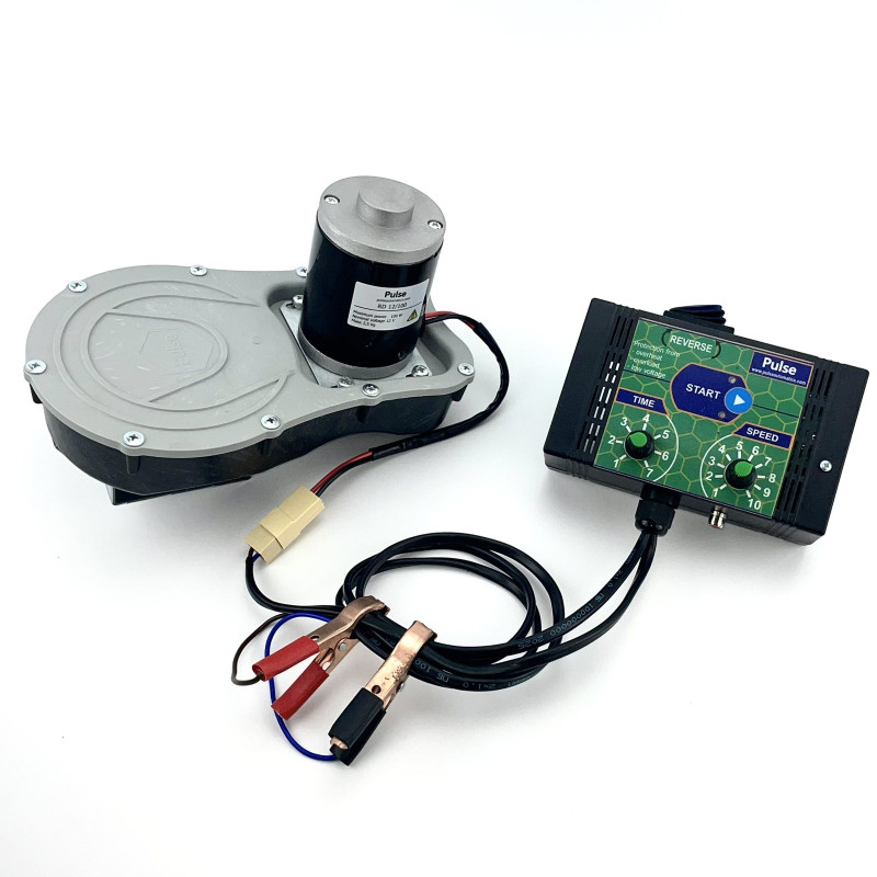
Electric Drive for Honey Extractor

Model RD1012A1

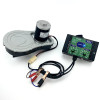
Included in the kit:

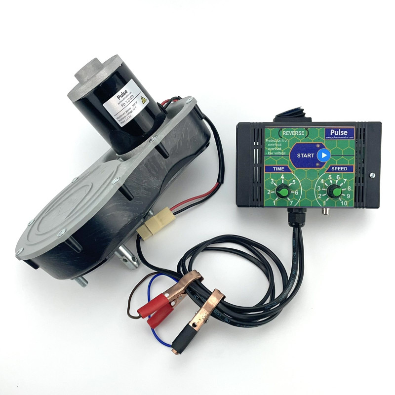
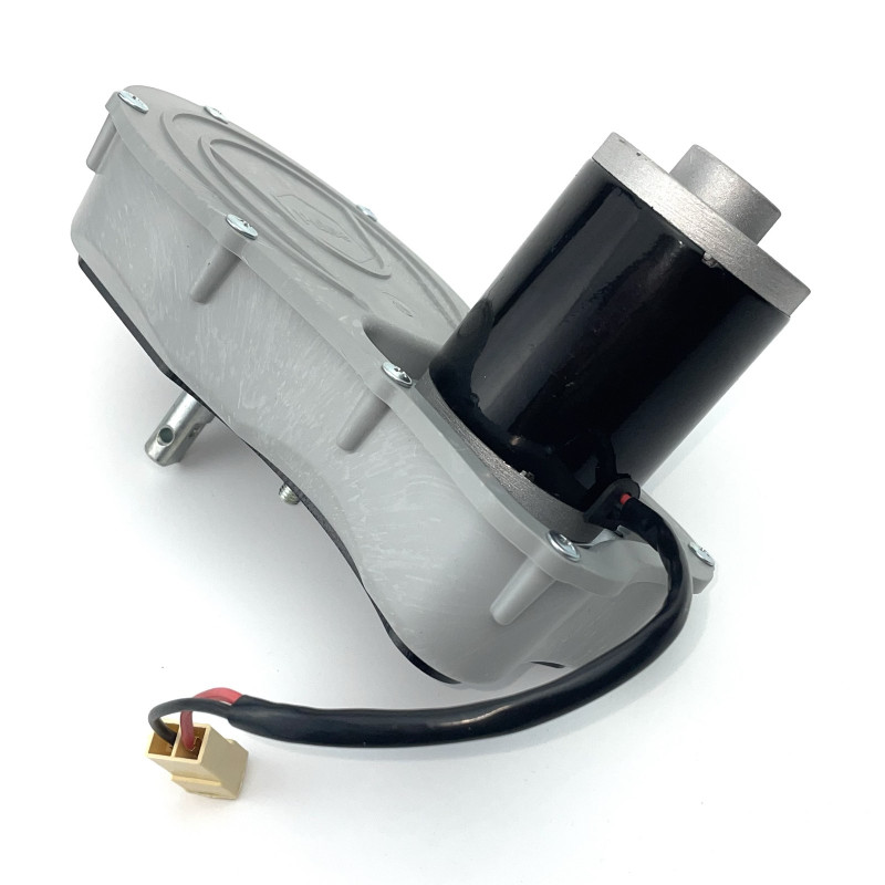
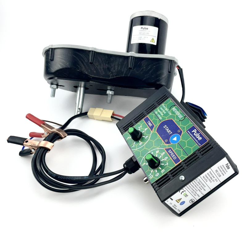
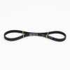
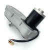
Belt gearbox – 1 pc.

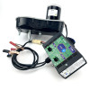
Mechanical control panel – 1 pc.


Technical Specifications:

Power: 100W
Voltage: 12V
Unloaded speed: 50–220 RPM


Power: 100 W

Supply voltage: 12 V

Rotor speed range: 50–220 RPM


Application:

Electric Drive for Honey Extractor Model RD1012A1

Designed for installation on honey extractors of ABB-100 and Charunka models, as well as Soviet-made models.

The electric drive mounts on the rotor shaft of the honey extractor, providing rotor rotation from 50 to 220 RPM, with a honey extraction time adjustable from 1 to 7 minutes. Motor control is performed by a modern high-frequency field transistor. During operation, the control unit continuously monitors input voltage, current draw, and temperature of key power components, ensuring reliability and protection from module failure.

Overload Protection.

If the current exceeds 4.5 A during operation, a red indicator lights up; if it persists for more than 8 seconds, the device enters emergency mode.

Under‑ and Over‑Voltage Protection.

If input voltage falls below 10 V or rises above 14 V, the control unit enters emergency mode.

Overheat Protection.

Prolonged high load due to mechanical failures of the extractor’s moving parts, or if honey contacts the rotor, may overheat the control panel. If temperatures exceed 100 °C, the control unit enters emergency mode.


Belt Gearbox Construction:

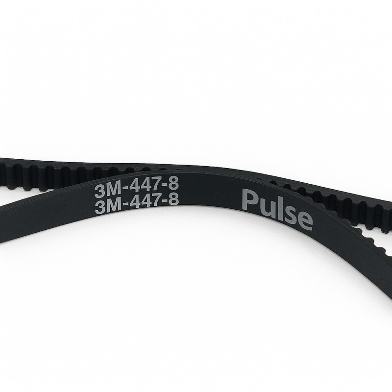
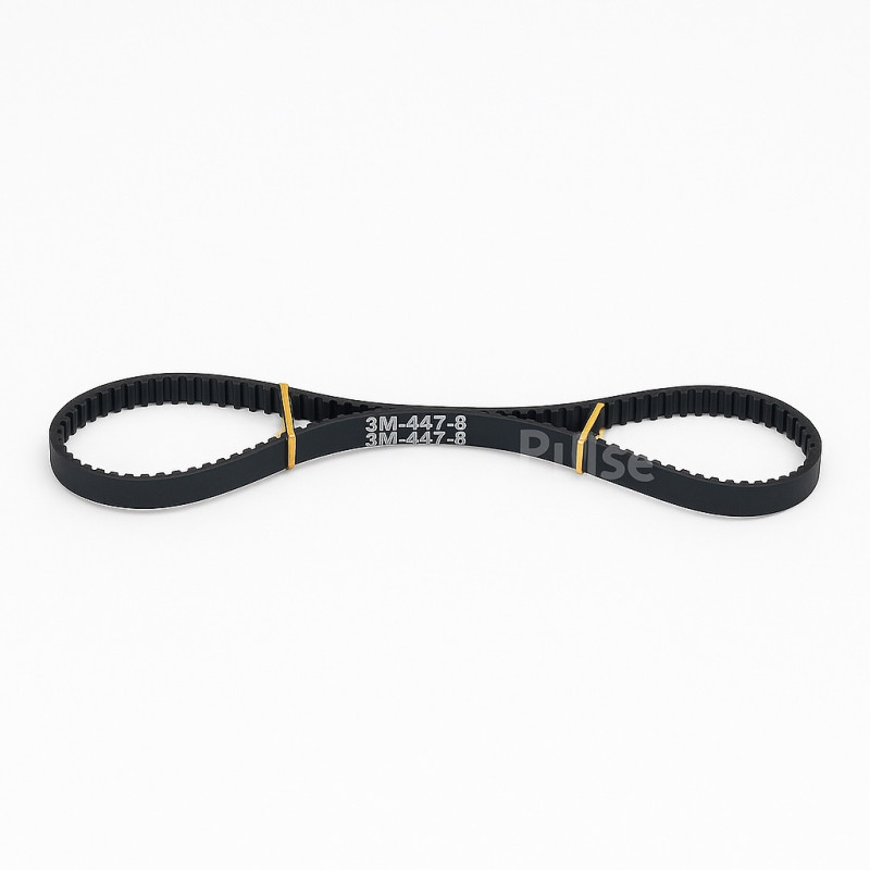
The belt gearbox consists of a 100 W high-efficiency electric motor, a toothed belt, a drive pulley, and a driven pulley. The gearbox base is made of 3 mm sheet steel coated with antibacterial paint. The drive pulley is aluminum; the driven pulley is primary glass‑filled polyamide. All rotating elements use ball bearings. The drive uses a GT3x391 mm toothed belt. The upper cover is made of high‑strength ABS plastic.


Service Life:

Our company conducted endurance tests on the gearbox assembly under load conditions simulating a 4‑frame Dadant extractor, used at medium-size apiaries with 10–50 colonies.

Service life estimates:

 – motor, drive and driven pulley – at least 10–20 years

 – ball bearings – at least 3–7 years

 – GT3x391 mm toothed belt – at least 2–5 years

User Manual – Technical Passport


Electric Drive for Honey Extractors

     This manual is intended to acquaint users with the operating principle, design, specifications, installation, and operation conditions.


  • Technical specifications:

PARAMETER


VALUE


Type:


Belt (GT3m 391×10 mm belt)

Power:


100 W

Allowed input voltage (V)


10–14 V (DC)

Rotor speed range:


50–220 RPM

Current limit (A):


4.5 A

Operating temperature range (°C)


+5…+45

Protection rating


IP20

  • Control panel protections include:
  • Over-current protection: max 4.5 A.
  • Protection against accidental REVERSE toggle.
  • Power module temperature protection.
  • Under‑ and over‑voltage protection.

Package contents:

Belt gearbox with 100 W DC motor – 1 pc.

Mechanical control panel – 1 pc.

Bracket for control panel – 1 pc.

Set of mounting hardware – 1 pc.

Technical passport – 1 pc.

Packaging box – 1 pc.


Application

     The drive can be installed on honey extractors from ABB‑100, Charunka, and Soviet-made models.

Purpose:

     Designed for installation on chordial and radial type honey extractors.

  • For chordial extractors of 2–6 frames (Dadant type), total load weight ≤ 24 kg.
  • For radial extractors, drum diameter ≤ 720 mm.


Installation and connection:


 Gearbox installation:

  • Before mounting, remove the upper shaft bearing of the honey extractor. The extractor should operate on the lower bearing (either ball or thrust ball‑roller depending on model) and the upper bearing located in the gearbox, which is designed for these conditions.

      If your honey extractor lacks mounting holes, you must drill them exactly at the center of the traverse, checking centering with measuring tools (tape measure, ruler). After that, install the gearbox.

  • Mount the gearbox assembly on top of the traverse and securely fasten it from below using M8 nuts. Fig 1.
  • Secure the gearbox shaft to the extractor shaft using a cotter pin. Fig 2.


IMPORTANT!

o Remove the original upper bearing with its housing!

o Securely fasten the gearbox shaft to the extractor shaft with a cotter pin.

o After installing the gearbox, ensure the extractor rotor rotates freely by hand, without noise or resistance.


Control Panel installation:

  • Mount the control-panel bracket; for Melisa 93 extractors, use the factory holes holding the traverse. If holes don’t align, we recommend drilling new ones. Fig 3.

If you have another extractor modification, drill mounting holes in the extractor’s rim, ensuring that the distance from the gearbox and panel connectors allows future connection.

  • Attach the control panel to the bracket. Fig 4.


Connection:

  1. Connect the gearbox-to-control‑panel plug.
  2. Connect the power leads (alligator clips) to a 12 V battery or a 12 V switching power supply, observing polarity.

     Power can be from a 12 V car battery or a 12 V/100 W switching power supply provided by the manufacturer.


IMPORTANT!

o Do not use low‑power power supplies below 100 W/8 A

o Do not use CHARGERS!

o Do not use homemade power supplies!

o Do not use toroidal power supplies from other manufacturers!

Control panel may fail! This is NOT COVERED BY WARRANTY!


Operation


  • Rotor speed adjustment “SPEED”

The control panel allows adjusting rotor speed from 50 to 220 RPM, using the “SPEED” knob marked 1–10.

  • Tip

Choose:

  • Unloading speed (speed at which a fully honey-loaded frame unloads without damage), depending on extractor model, size, condition of moving parts, and power supply. Usually 90–140 RPM depending on temperature, honey variety, and comb condition.
  • Extraction speed (speed at which honey is fully extracted without damage), usually 110–190 RPM depending on temperature, honey variety, and comb condition.


  • Working time adjustment “TIME”:

The control panel allows setting rotor running time from 1 to 7 minutes using the “TIME” knob marked 1–7.

Time is set before pressing “Start”. During operation, time adjustment is locked.

  • Tip

Choose:

  • Unloading time (time to unload a full frame), depending on temperature, honey variety, comb condition. Usually 1–3 minutes.
  • Extraction time (time to fully extract honey from a frame), depending on temperature, honey variety, comb condition. Usually 1–3 minutes.


  • Rotor direction control “REVERSE”:

The control panel allows reversing rotor rotation using the “REVERSE” toggle switch.


IMPORTANT!

o Do NOT toggle “REVERSE” while rotor is spinning!

     Wait for complete stop before switching “REVERSE”.

Improper use may damage the gearbox and control panel! Not covered by WARRANTY!


Drive operation:


     When power is applied to the control panel, it enters standby mode, with the green indicator blinking once per second, signaling that all parameters are normal.

     In standby mode, you can adjust Speed, Time, and Reverse.

     Once the START/STOP button is pressed, the panel begins the set program of TIME and SPEED. After the set time ends, it issues a STOP command, counts down a 10‑second lockout period, and returns to standby.

     If START/STOP is pressed prematurely, it issues STOP, initiates a 10‑second lockout, and returns to standby.


Emergency mode signals


  • Over‑current protection: max 4.5 A.

     If current exceeds 4.5 A, the control panel lights a red indicator. If sustained for more than 8 seconds, it enters emergency mode with rapid red LED flashing. Reset via START/STOP.


  • Protection against accidental “REVERSE”.

     Switching “REVERSE” while running stops the drive instantly, entering emergency mode with alternating red and green LEDs. Reset via START/STOP.


  • Power module temperature protection.

     If temperature exceeds 100 °C, the panel blinks red, signaling over‑temperature. It resets automatically once temperature falls below 70 °C.


  • Under‑ and over‑voltage protection.

If voltage drops below 10 V or exceeds 14 V, the panel lights green, signaling under/over‑voltage, entering emergency mode. It resets automatically once voltage stabilizes.


IMPORTANT!

     If during rotor acceleration the red indicator lights for more than 2 seconds, check bearings, seals, sleeves. The rotor should spin freely by hand.

     Control panel overheating may occur if honey contacts the rotor.

     If the panel switches to STOP during acceleration, check the power supply or battery charge status.


  • Maintenance and repair:


During operation, wear occurs on:

     – Toothed belt

     – Bearing

     Replace belt and adjust tension so it’s neither slack nor overly tight, which could cause failure.

     Replace bearings by fully disassembling the belt gearbox.


IMPORTANT!

     We recommend contacting the manufacturer’s service for maintenance; you’ll receive quality spare parts and consumables.

Reviews
0 / 5
average product rating
0
0
0
0
0

There are no reviews for this product, be the first to leave your review.

Answers & questions

No questions about this product, be the first and ask your question.

RD1012A mechanical ABB-100, Charunka. ELECTRIC DRIVE FOR HONEY EXTRACTION (12 V 100 watts) with connector for connecting the Start Stop pedal
4 300 грн.